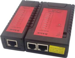
RJ45 and RJ11 Universal Network Cable Tester
KSh700.00 Ex.VAT
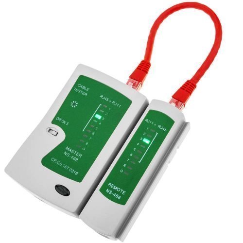
LAN Universal Network Cable Tester
Universal LAN tester


A Network Cable Tester is a tester of network cables with twisted pair, straight and crossover wire configurations. Resolving network connectivity issues is often a mere process of elimination.
Main Function: Verify RJ11, RJ45 cables
Tracking Type : RJ11 & RJ45
Power: 9V Alkaline battery
Following are abnormal connections:
If one cable, for example, cable NO.3 is open-circuited, the two NO.3 lights of the main tester and remote tester will not turn on.
If several cables are not connected, several lights will not turn on respectively. If less than two cables are connected, none of the lights is on.
If two ends of a cable are disordered, for example, NO. 2and NO. 4, then displays on:
Main tester: 1-2-3-4-5-6-7-8-G
Remote tester: 1-4-3-2-5-6-7-8-G
If two cables are short-circuited, neither of the corresponding lights is on of the remote tester while the main tester remains unchanged.
If three cables, including three, are short-circuited, none of the corresponding lights is on.
If test patch panels or wall plate outlets, two cables that can match each other (RJ45) will be connected to the tester.
This network cable tester helps determine whether or not a network cable is the source of the problem. To use, connect one end of the network cable to the “Master” controller and the other end to the “Remote”.
Turn the switch found on the Master controller to the on position to begin testing. If the network cable is working properly, the Master controller and the Remote will illuminate sequentially with green lights.
When testing cables with RJ-11 connectors, lights 1 through 6 should illuminate. When testing cables with RJ-45 connectors, lights 1 through 8 should illuminate.
How to Test Your Ethernet Cables Using a Network Cable Connector.
The device is Super-simple to use!
1) Install a 9V battery
2) Connect your “test” cable to the appropriate jacks on the Main UNit and “Remote” unit
3) Turn it on. The RED “POWER” LED will start blinking: FAST in the “ON” position, SLOW in the “S” position
4) Watch the GREEN LEDs on the Main unit sequence from “1” to “G”, then repeat until you turn the Main unit OFF or disconnect the cable. Place the POWER switch in the “S” (Slow) position to better observe the LED sequencing.
5) The GREEN LEDs on the “Remote” unit will sequence with the Main unit’s LEDs, with the “Remote” LEDs indicating which wires are connected to each other.IDEALLY, one ONE LED on each of the Main and “Remote” units will light in sequence. If NO LED on the “Remote” unit lights for a given Main unit LED, that wire IS NOT CONNECTED between the two points. READ THE INCLUDED DIRECTION SHEET to interpret other “LED ‘patterns, etc.’”
Be the first to review “RJ45 and RJ11 Universal Network Cable Tester” Cancel reply
You must be logged in to post a review.
Related products
Tools & Accessories
Networking Equipment
Tools & Accessories
Heavy Duty RJ45 Crimp Tool for Rj 11 4p, RJ12 (6P) and RJ45 (8P)
Tools & Accessories
Tools & Accessories
D-Link Cable Tester Detected Cable Type RJ-11 RJ-45 Black NTL-CT-001



Reviews
There are no reviews yet.